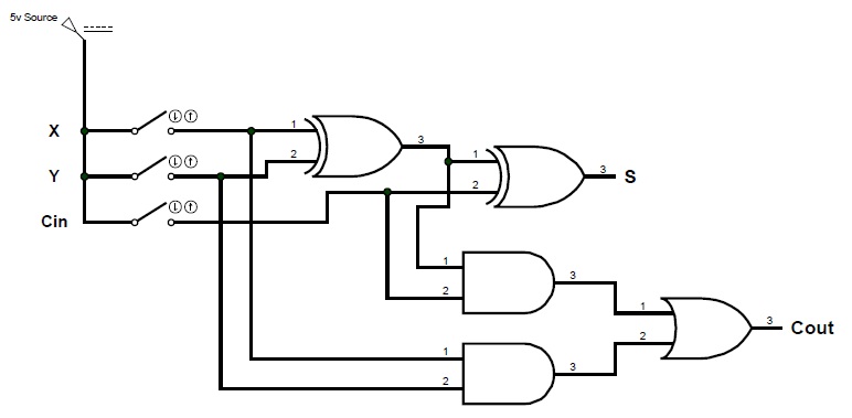
Circuit Diagram 2 Bit Full Adder
Adder circuit proposed Adder combinational circuitverse parallel adders Adder theorycircuit
Full-Adder Circuit, The Schematic Diagram and How It Works – Deeptronic
Adder bit circuit logic half make gates diagram comparator two electronics first memory questions cout difference between there only second Solved build the adder-subtractor circuit from page 18 from Adder circuit diagram schematic bit works figure
Binary adder and subtraction circuits along with its various types
13+ full adder block diagramAdder bit logic implementation circuit half adders numbers electronics diagram two bits carry schematic ripple digital add build implement together Ece logic circuitFull-adder circuit, the schematic diagram and how it works – deeptronic.
Adder subtractor logicFull adder Circuit diagram of a one-bit full adder using the proposed technique inFull adder circuit diagram.

11+ 4 bit adder circuit diagram
Block diagram of basic full adder circuitFull adder circuit: theory, truth table & construction Adder bit ripple carry schematic fa lab ac cs code makefile inf labs courses teaching edFull-adder circuit, the schematic diagram and how it works – deeptronic.
2-bit adder implementationDigital electronics and logic design Schematic adder ripple conventionalFigure (3) full adder..

Logic gates
Full-adder circuitAdder cmos soi Adder bit diagram schematicAdder alu nor nand.
Adder circuit electronics outputsAdder circuit 2.2: proposed full adder circuitAdder circuits electrical circuit figure.

Adder implemented adders joining
Adder carry circuit sum implementation electronics logic output simplified two outputs tutorial combinational circuits both shows below figureAdder half subtraction encoding circuits Adder circuit diagram schematic works figureCircuit adder bit logic ece generate truth table now.
Adder vhdl circuits truth cktAdder circuit construction binary circuits ibm sourav gupta Vhdl tutorial – 10: designing half and full-adder circuitsInf2c-cs lab 2: systemc basics.

Adder circuit bit logic two liucs
Schematic diagram of a 2-bit adder: (a) 2-bit half adder is implemented(a) function of a 2-bit full adder. (b) schematic diagram of two .
.


